Polarisation of Light Investigation
| ✅ Paper Type: Free Essay | ✅ Subject: Physics |
| ✅ Wordcount: 1753 words | ✅ Published: 12 Mar 2018 |
- Valentin Haemmerli
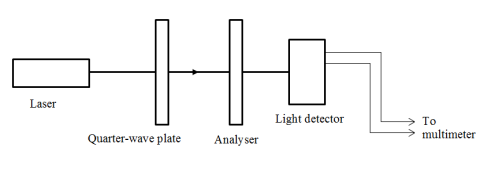
Abstract. An optical system consisting of a laser, a polariser, a quarter-wave plate, a prism, and a light detector connected to a multi-meter was used to find the transmission axes of the polariser and the quarter-wave plate, find the angle of polarisation of the laser relative to the optical axis and investigate the quality of the polariser and quarter-wave plate by comparing the theoretical and experimental values of degree of polarisation for linear, circular and elliptic polarisations. These were found to be 0.98±0.03 compared to 1 for linear, 0.18±0.03 compared to 0 for circular and 0.59±0.03 compared to 0.65 for a particular ellipse.
- Introduction
Polarisation of electromagnetic radiation is a fundamental phenomenon arising directly from the wave properties of light. Polarisation of light in the visual spectrum has many commercial applications such as stress analysis of birefringent materials[1, 2], sugar content analysis in the brewing industry and in food chemistry[1], liquid crystal displays [2] and in sunglasses. In addition to these applications, polarisation of light has a number of important scientific uses, including “determining the refractive indices, absorption constants and reflecting power of …highly absorbing materials” [1].
There are three different cases for polarised light; linear, circular and elliptical. The aim of this investigation was to calibrate the optical system and subsequently use it to analyse transmission intensities for each of these types, and compare the respective degrees of polarisation to theoretical values.
- Theory
- Polarisation Types
Electromagnetic waves have electric and magnetic field components propagating as sinusoidal waves where the directions of the electric field vector is perpendicular to both the direction of the magnetic field vector and to the direction of propagation at all times. Due to this constant relation between electric and magnetic field vectors, we can describe polarisation in terms of electric field only for simplicity.
Linear polarisation is the case where the x and y components of electric field for a wave traveling in the z-direction are varying in phase with each other, so they are both at their maxima at the same time, and both at their minima at the same time, and the electric component of the wave is always in the same plane. This is shown in Figure 1a).

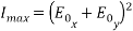
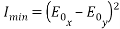
Circular polarisation, shown in Figure 1b), occurs when the x and y components of the electric field vector have the same amplitudes and have a phase difference of π/2, or π/2 plus an integer multiple of π. The end point of the resulting electric field vector traces out a circle in the x-y plane, which translates to a helix once time is taken into account.
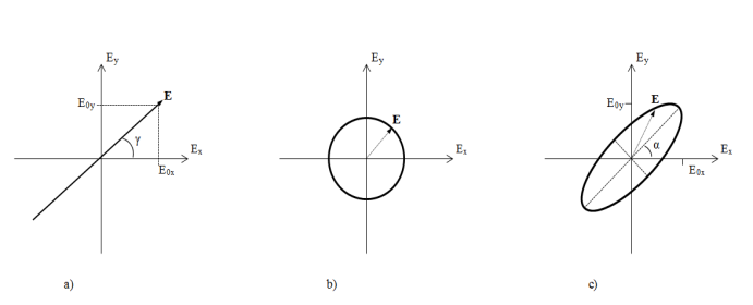 Elliptical polarisation, of which circular polarisation is merely the special case when the amplitudes are equal and the phase difference is
  where
where  . Elliptical polarisation is therefore any case for which the end point of the electric field vector traces out an ellipse in the x-y plane. This is shown in Figure 1c).

- Brewster’s Law
Brewster’s Law states that for a beam incident on a flat horizontal glass surface of a prism at the Brewster angle, given by
 ,(1)
,(1)
where  is the refractive index of the prism, only the component of the beam with polarisation parallel to the incident plane is reflected. This fact can be used to determine the polarisation of the incident beam after it has passed through the analyser. By rotating the analyser until there is no reflected component the beam is polarised vertically and hence has not component in the horizontal direction.
- Quarter-wave plate
A quarter-wave plate is an optical device which is made of two materials with different refractive indices which has the effect of introducing a phase difference of π/2 between the perpendicular x and y component of the electric field vector for light of a particular wavelength. The quarter-wave plate has two perpendicular transmission axes. A quarter-wave plate can therefore be used to change the polarisation of the incident light from linear to elliptical and in the simple case of the ellipse, circular.
- Degree of polarisation
The equation used to find the degree of linear polarisation of light for transmitted intensities measured for angles of analyser is
 ,(2)
,(2)
where I is intensity.
- Experimental Method

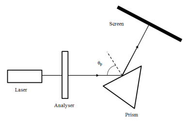 We first found the transmission axis of the Polaroid analyser using Brewster’s Law of horizontal polarisation using the set up in Figure 2.We started at an approximate value of Brewster’s Angle using n=1.6 for the refractive index of the prism. We set the incident angle to this, and then rotated the analyser until no light was reflected from the face of the prism, but light was still transmitted through the analyser. By slight changes of the incident angle on the face of the prism and the angle of the analyser to minimise the transmission, we found the transmission axis of the Polaroid analyser.

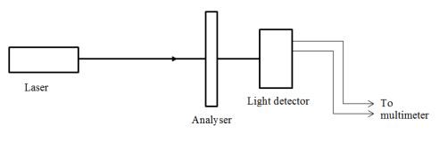 We found the degree of polarisation of linearly polarised light using the set up in Figure 3, by rotating the analyser through 360º and noting the transmitted intensity detected by the light detector and multi-meter in volts. Plotting the intensity as a function of angle and comparing it to a theoretical plot of transmission from Malus’ Law, we also found the angle at which the laser beam was polarised.

 Using the set up shown in Figure 4 we found the transmission axes of the quarter-wave plate. With the analyser set to an angle perpendicular to the angle of polarisation of the laser beam (i.e. a minimum intensity), transmitted intensity was measured for angles between 0 and 360º of the quarter-wave plate. The minima of this dependence correspond to the transmission angles of the quarter-wave plate.
Once the transmission axes were found, the quarter-wave plate was set to an angle of one of the transmission axes plus 45º to give circularly polarised light. The intensity was measured as a function of the angle of the analyser. This was used to find the degree of polarisation of circularly polarised light by rotating the analyser through angles from 0 to 360º.
Finally we tested for a theoretical value of elliptical degree of polarisation of 0.65 by turning the quarter-wave plate 22.7º past one of the transmission axes and once again rotating the analyser through 360º and measuring intensities to give an experimental degree of polarisation.
The error in the analyser angle and quarter-wave plate angle was determined by observing the range of angles over which the intensity did not change. This was ±2º in both cases, and when both the analyser and quarter-wave plate were on the optical bench this gave a combined error of ±4º. The ambient light reading was taken to eliminate a systematic error in intensity readings. This was found to be 0.00 V.
- Experimental Results
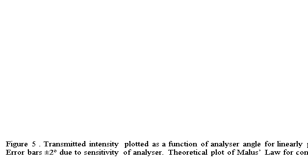 The degree of polarisation of the analyser is 0.98±0.03 from the maximum and minimum intensities in Figure 5 and equation (2). The error comes from the uncertainty in the measurement of the intensity. The angle of polarisation of laser beam is 10±2º. This was determined from the angle difference between the experimental data and the theoretical plot of Malus’ law. The error is given by the error in analyser angle.
The transmission axis of the analyser runs from 170º to 350º ±2º, this is given by the maxima of the experimental data in Figure 5.
The transmission axes of the quarter-wave plate are 20±4º to 200±4º and 110±4º to 290±4º from the minima in Figure 6, corrected for the angle of polarisation of the laser beam.
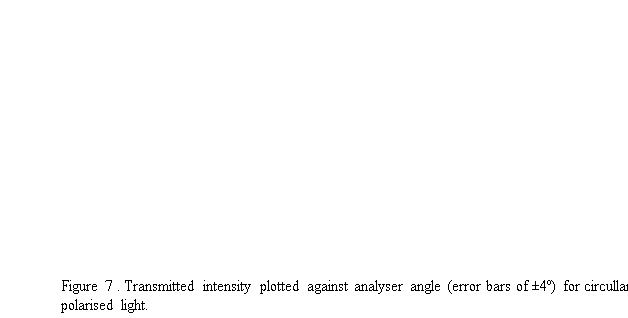
The degree of polarisation of circularly polarised light is 0.18±0.03 from the maximum and minimum intensities in Figure 7. 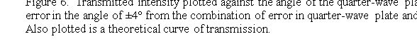
Theoretically the quarter-wave plate should be at one of its transmission axes plus 23±2º for a degree of polarisation of 0.65. At this angle the experimental degree of polarisation was 0.59±0.03 from the maximum and minimum intensities in Figure 8.

- Discussion
The error in the sensitivity of the polariser and quarter-wave plate are much greater than the accuracy of the scales on the polariser and quarter-wave plate. The errors are found to be ±2º for each, while the accuracy of the scale is ±0.5º. This is far too small because intensity did not change over such a small change in angle.
One possible reason for such a large difference between theory and experimental values for degree of polarisation for the case of elliptical polarisation, 9.2%, is that the quarter-wave plate was designed to give a phase difference of π/2 for a specific wavelength of light due to the dependence of refractive index on wavelength. The wavelength of our laser was not the same as this design. The difference could be reduced by using a more suitable laser or quarter-wave plate.
The theoretical degree of polarisation for circular polarisation settings of the quarter-wave plate and analsyer is 0, compared to the 0.18±0.03 found experimentally. Similarly, the analyser was not ideal, imperfectly blocking components perpendicular to the transmission axis. The theoretical degree of polarisation for the analyser is 1, while experimentally we found it to be 0.98±0.03. The contribution to the error from the quarter-wave plate is therefore larger than that from the analsyer.
There are two possible reasons for imperfect circular polarisation. The first of these is that the quarter-wave plate was set to the wrong angle, not at 45º to a transmission axis. This would lead to an error in the degree of polarisation of approximately twice the error in the angle, or approximately 4. This is far too large for our degree of polarisation and therefore unlikely, since the difference between theory and experiment is only 0.18. The other reason is that the quarter-wave plate did not shift the phase of one component of polarisation by π/2. Then the difference is approximately the difference between the theoretical phase difference and the actual phase difference. This is the more likely case, as discussed above, the quarter-wave plate is designed for a specific wavelength of light.
- Conclusions
We investigated three types of polarisation of light using an analyser and a quarter-wave plate. We found degrees of polarisation for each type, and compared them to their theoretical values. This gave us an idea about the quality and suitability of the analyser and quarter-wave plate for our laser, with the quarter-wave plate contributing the largest amount to the difference between the theoretical and experimental polarisations. In the process of finding these values we also determined the transmission axes of the analyser and the of the quarter-wave plate.
- Appendix
- Derivation of the angel of the quarter-wave plate for degree of polarisation 0.65
From equation (2): 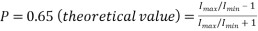
 ,
,  (3)
(3)
 ,
,  (4)
(4)
From (3) and (4),
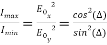 , (5)
, (5)
where  is the angle offset from the transmission axes of the quarter-wave plate and
  is the component of the electric field vector.
This gives us, from equations (1) and (5),
 . (6)
. (6)
- References
[1]C. A. Skinner, “The polarimeter and its practical applications,” Journal of the Franklin Institute, vol. 196, pp. 721-750, 1923.
[2]P. A. Tipler and G. Mosca, Physics for scientists and engineers : with modern physics, 2008.
1
Cite This Work
To export a reference to this article please select a referencing stye below:
Related Services
View all


DMCA / Removal Request
If you are the original writer of this essay and no longer wish to have your work published on UKEssays.com then please click the following link to email our support team:
Request essay removal