Automation of the Tapping Machine
| ✅ Paper Type: Free Essay | ✅ Subject: Mechanics |
| ✅ Wordcount: 1633 words | ✅ Published: 11 Sep 2017 |
CAREER EPISODE 2
INTRODUCTION
CE 2.1
The second career episode is based on an experience that I gained after performing a group project as a student of last semester of Bachelor Degree. The project was title “Automation of the Tapping Machine”. I completed my Bachelors of Engineering Technologist in Mechatronics from Chisholm Institute, Dandenong, Australia. The project was completed in 13 weeks’ duration, from March 2016 to May 2016. It was undertaken under Prof. Dr. Tharshan Vaithianathan and Prof. Masoud Goudarzi and was a part of my industrial training at R & I Instrument and Gear Co. Pty. Ltd.
BACKGROUND
CE 2.2 Nature of project
Finding a solution that saves cost and time within production is the biggest responsibility of engineers when manufacturing. Automation is required in all the industry to improve efficiency, maintain consistency and speed, reduce waste, and maintaining quality to compete the global market. There were issues arising in tapping and gear cutting machine which lead to wastage of cost and labor time for the company R & I Australia. To provide a multiple tapping device at a time and to eliminate the manual adjustment process of the XY table, I had proposed this project. In my project, I had to accomplish all the business goals and objectives assigned to me within defined budget and time parameter. And to minimize the impact within the affected units to standardized the business operations.
CE 2.3
The goal of implementing the tapping machine is that it:
- Facilitates coordination and information sharing both internal and external to the organizations.
- Will provide better finished products.
- Enhances the ability and effectiveness of the team to perform their jobs.
- Easy use
- Provides an open, flexible, reliable updated technology.
CE 2.4 Objectives
The primary objective was to address the issue of production and give a possible solution that rectifies it and helps to improve the efficiency of the production and specially in terms of tapping machine and Saws department and to partially optimize the cost. Basically, the whole project is made up of 2 different objectives which is completed to solve the issue. The idea is to achieve a high degree of accuracy in the process. Also, to learn about how stepper motors are programmed through G-coding along with the Arduino board and g shield.
CE 2.5 The chart of organizational structure


CE 2.6 Duties
- I started with studying various solutions that fit my problem statement.
- I researched and surveyed on automation, gears, latest equipment from FSM & SMC
- Learnt how CNC shield is operated and G code is programmed.
- Performed online and practical testing on the operating machine.
- Compared various components before selecting them.
- Researched on drive mechanism, stepper motors, wheel shafts and pulleys.
- Prepared various engineering drawing for implementation of my project with the help of engineering tools.
- Diving and providing time slots to team members.
- Maintaining balance and peace to avoid conflict among each other.
- Kept good relations with supervisor.
- Reporting the development of the project to the lab supervisor and coordinator.
PERSONAL ENGINEERING ACTIVITY
CE 2.7
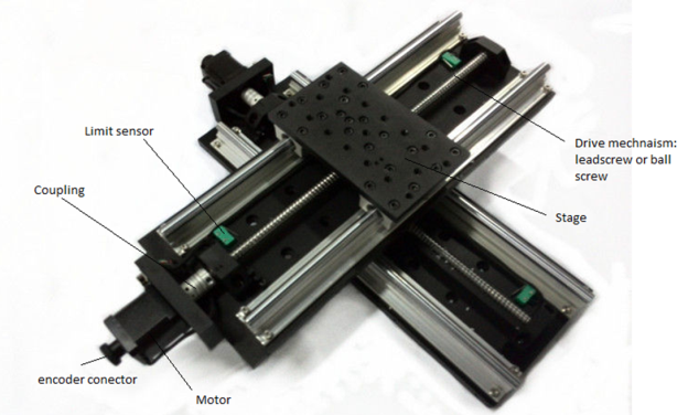
I first observed the current scenario of the work procedure and the machine operation. Based on my notes, I decided to remove the current manual XY table along with the vice and add a new system motorize stage. The new proposed XY table system will be placed on the base plate of the tapping machine and then further connected to the CNC shield for programming. The table is made such that it holds few work pieces at the same time. Once the work piece is kept and placed on the table, a G code program controls the tapping operations that is obtained from the USB device connected to the CNC shield. The XY table is designed in solid works such that it moves in X and Y directions. There are stepper motor drive shafts that are connected and when they rotate it drives the lead screws connected to it and move the stage in X and Y directions.

CE 2.8
The below image shows the proposed XY table and its related components. It is designed keeping in mind the future height of XY table together with the vice along with the length of the drill bite. The drill head is kept and positioned such that the distance from the middle of the base plate to end in Y axis is 90mm. the stroke movement of the table in the direction of Y axis from the center position is assumed to be 50mm and in the direction of X axis it is 100mm. The selection procedure of XY table involved range of steps. At the first stage, it was required to take up the measurements of the current set up that was in use. Later stage was designing, which was done to find out various variables that are related to the table.
CE 2.9
Based on certain assumptions and from the current scenario, the calculations for the variables was done and considered as shown in the table below. With these values, selection procedure was carried out for various components and its parameters. For my project a drive mechanism was required which rotates the motor to the table and helps the XY table o move, so for this reason I decided to use ball screw drive mechanism which is ideal for my situation because of its high stiffness and ability for short acceleration and declaration. The motor was selected with the help of online software that helps for various calculation. Arduino G shield is used as it is a suitable hardware solution for CNC motion controlled systems. I made use of engineering tools for drawing each solid work piece and component considering the minute details and its precise values to achieve the highest accuracy level.
|
Maximum payload |
Stroke |
Precession |
Speed |
|
7kg |
XY:200mmx180mm |
20 microns |
max: 25mm/sec |
CE 2.10
After completing the above XY table, I had to automate the rotation of hand wheel which controls the vertical movement. And the important point for consideration was the depth of the gear cut. So, it was important to track the vertical movement of the axis of the machine and solution for replacing the manual hand wheel with mechanical automated machine. After all the brainstorming process, I decided to use pulley belt mechanism using a steeper motor to replace the current manual hand wheel. By using this, it would provide high speed of production, accuracy, it will be time saving and less labor involvement which would result in safety.
CE 2.11
I used CAD software and other engineering software to design the structure of the components that will be made to use based on the requirement and calculations taken up. The components were compared for price and the budget was kept in mind. It was necessary to take precaution in selecting the correct component as it would affect the whole system. The components used are:
- Stepper motor – required to produce torque to turn rotating wheel shaft for gear cutting operations.
- Small pulley for motor – 14mm inner diameter, selected considering the conditions it met.
- Large pulley for turning wheel shaft – 42mm maximum bore diameter
- Time belt to transfer momentum between both pulley – polyurethane cantilena belt was chosen, which had high grade wire and tension with high flank load capacity.
- Stepper motor driver – to manage the running capacity of the stepper motor
- Rotary encoder – it is basically used to detect original position of the shaft. It converts mechanical displacement signals to electrical signals.
- Arduino board for programming – Arduino Uno r3
CE 2.12
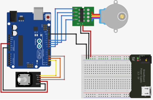
After coming to the conclusions and deciding of the components, I plotted an electrical connection diagram that depicted the structural layout of all the electrical connections that were required between the Arduino UNO board, motor, and the power supply to run this mechanism. The Arduino board was connected to the encoded and the motor. From the diagram, the pin number 8-11 of the board are used for controlling the stepper motor. And the pins from 2 to 4 are used for encoder. Programming is done to deliver the reference data to regulate the motor and encoder. With the help of 5V supply that is received by the UNO board, it supplies the power to the encoder also and both are grounded properly so that same reference voltage is provided to the encoder and the power supply.
CE 1.13
After completing the hardware work and when the connection was completed. I performed a troubleshooting, to check the functioning of the mechanism is proper. I used many different engineering software to test the system. Luckily, I didn’t come across any major issues while implantation of the project. I only had problems in decided the accurate component that would meet the requirements of my project. I also introduced new engineering skills and workshops in my project such as latest equipment’s from FSM and SMC, HMI systems, G shield for automated dispatch, and automated field reporting software by using interfaces like G-coding, C++, AFR and CAD.
CE 1.14
As I was leading the whole project, I was responsible for managing my group mates. I had to regularly keep updates on their progress and maintain one on one relationship to achieve success in my project. I also maintained good relations with my university supervisors and the company engineer under whom I was getting trained.
SUMMARY
CE 1.15
I accomplished the goals and objectives assigned to me by the company. I presented them a well-planned and working device which would benefit in their production. I applied various engineering knowledge that I learnt from my bachelor’s degree. I also introduced new techniques and mechanism that was beneficial and appropriate for my problem summary. I learn new software and learned to prepare a budget and function the project in that assigned budget. I cultured myself into the corporate world and adapt corporate behavior and skills. A project thesis and a presentation of my work was submitted on completion of my work.
Cite This Work
To export a reference to this article please select a referencing stye below:
Related Services
View all


DMCA / Removal Request
If you are the original writer of this essay and no longer wish to have your work published on UKEssays.com then please click the following link to email our support team:
Request essay removal