Small Scale GTL (STG Plus) Plant
| ✅ Paper Type: Free Essay | ✅ Subject: Engineering |
| ✅ Wordcount: 3781 words | ✅ Published: 31 Aug 2017 |
Course: Natural Gas Processing Technology (ENCH 609, Winter 2017)
PROJECT TITLE
GTL: Syngas to Gasoline (STG Plus)
Professor: Dr. Nashaat Nassar
List of figures and tables:
- Fig 1. Schematic sketch of the STG+ system (from Primus Green Energy TM) .. (6)
- Fig 2. Sensitivity Analysis for case 62.5 MMSCFD (14)
- Table 1. Economic Indicators for project evaluation (Detail calculation in Appendix).. (15)
Appendix:
- Fig 1. Operating GTL plants on the world map [The Oil & Gas Year, 2015] . (21)
- Fig 2. Simulation flow chart developed for the project (from Aspen plus V 7.2 & Microsoft Visio 2010) (22)
- Table 1: Used compounds and Values of yields for reactor 4 in the model …. (19-20)
- Table 2: Economic Evaluation for case 1: 10 MMSCFD ..(23)
- Table 3: Economic Evaluation for Case 2: 62.45 MMSCFD (24)
- Table 4: Mass balance of streams 1-22 for Case 1: 10 MMSCFD ………….(25-26)
- Table 5: Mass balance of streams 1-22 for Case 2: 62.45 MMSCFD .. (27-28)
Abstract:
The world’s energy demand is growing exponentially and to meet this demand, bringing new supply sources to the market is extremely critical. Natural gas resources are plentiful, geographically diverse and currently also the cleanest burning fossil fuel. Gas to Liquids (GTL) is a chemical process that transforms natural gas or other gaseous hydrocarbons into high quality liquid products that would otherwise be produced from crude oil [Shell Global]. GTL creates an additional opportunity to monetize a country’s resource of natural gas by turning them into high quality liquid fuels. GTL products are colorless and odorless hydrocarbons with very low level of impurities.
The purpose of this project is to simulate a small scale GTL (STG Plus) plant that converts 10 MMSCFD of rich-methane natural gas into 672 BBL/day of gasoline. The first step of the STG Plus process is called “steam reforming” and it consists of the reaction between the methane in the natural gas with abundant water. The second step of the process is the reaction between the hydrogen, and the carbon monoxide producing methanol. The methanol thus formed will be converted to dimethyl ether (DME) and finally, the DME will be dehydrated, producing gasoline. The project will also highlight the difference between two major GTL technologies: Fischer Tropsch and STG Plus. An economic evaluation was conducted to check the viability of this process and at 10 MMSCFD conversion of methane; the project proves to be economically profitable, with an NPV value of $14.66M at 10% discount rate. It was also determined that if the production of gasoline increases to over 4,100BBL/day, the profitability of this project will increase significantly.
1.0. Introduction
1.1. GTL Technology and the World
Gasoline to Liquid (GTL) is a technology that converts natural gas or other gaseous hydrocarbons into high quality liquid products like gasoline or diesel fuel, otherwise produced from crude oil []. GTL products are colorless and odorless hydrocarbons with very low level of impurities. Refineries can also use GTL to convert some of their gaseous hydrocarbon waste products into valuable fuel oil which can be used to generate income.
The world’s first commercial GTL plant was opened by Shell in Bintulu, Malaysia in 1993. In 2011, the largest GTL plant, Pearl GTL was opened in Qatar [Shell Global]. Figure 1 in the Appendix shows all operating GTL plants and their corresponding locations on the world map.
1.2. GTL Origin
In 1920’s, when Germany found itself short of petroleum but with ample reserves of coal, GTL and Coal-to-Liquids (CTL) technologies were pioneered using a process known as Fischer-Tropsch (F-T) synthesis (Heng et al. 2004). Methanol-to-gasoline (MTG), Mobil’s synthetic gasoline process, based on the transformation of methanol to hydrocarbons using zeolite catalysts, was the first major synfuel process development in half a century since the development of the Fischer-Tropsch process (Frerich J. Keil, 1998).
1.3. Gas-to-Liquid (GTL) technology
Gas to Liquids (GTL) is a refinery process that converts gas or other gaseous hydrocarbons into products with longer carbon chains. Gasoline and diesel fuel are classic examples. Gases with a high concentration of methane are transformed into liquid synthetic fuels following two methods: direct transformation – using processes without the presence of catalysts that convert methane to methanol or by using syngas as a midway product, such as in the Fischer Tropsch, Syngas to Gasoline Plus and Mobil processes.
This project will focus on designing a small scale Syngas to Gasoline (STG) plus plant that uses methane rich natural gas as feed and converts it to high quality gasoline and other products.
2.0. Syngas-to-Gasoline plus (STG+) process
STG+ process was derived from the MTG (Methanol-to-Gasoline) process, which was developed by Mobil in the 1970’s. This technology directly converts natural gas-derived syngas into drop-in gasoline and jet fuel through a catalytic thermo-chemical single-loop process that minimizes complexity, improves product quality and yield. The “plus” in STG+ stands for the alternate end products yielded by the process.
The STG+ technology is currently operating by Primus Green Energy company in Hillsborough, New Jersey at pre-commercial scale with a production of 100,000 gallons (approximately) of distinct quality gasoline per year from natural gas with surpassed performance of the STG+ system and catalyst and 720 hours of continuous operation. The STG+ process consists of the following operating steps in one continuous process loop. It comprises of Syngas generation by steam reforming method, four fixed bed reactors in series and a two phase separator.

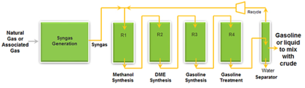
Figure 1: Schematic sketch of the STG+ system (from Primus Green Energy TM)
2.1. Syngas Generation by Steam reforming method
The first step in the STG+ process is to convert the natural gas feed into syngas or synthesis gas which is an intermediate gas feed for many different petrochemical processes. This processing basically removes contaminants, such as mercaptans, sulfides, mercury and any others that can compromise the various catalysts’ performance that are used in the STG+ reactors before it is fed to the syngas generation unit. Either partial oxidation or steam reforming processes are used for syngas production.
Steam reforming process is widely used to generate syngas for feedstock in different petrochemical processes. A mixture of hydrogen, carbon monoxide, carbon dioxide, and unconverted methane and steam are formed when methane reacts with steam in the presence of a catalyst such as Nickel or Rhodium at high temperature (800-1000 C), high pressure (20-40 bars) and steam-to-carbon ratio varying between 1.8 and 4 in the steam reforming process which is highly endothermic in nature (Mbodji et al., 2012).
The possible reactions are:
- The steam methane reforming reaction (SMR)
CH4 + H2O ⇄ CO + 3H2 [ΔH = +206 kJ mol-1] (strongly endothermic).. (1)
- The water-gas shift (WGS)
CO + H2O ⇄ CO2 + H2 [ΔH = -41 kJ mol-1] (moderately exothermic) . (2)
The product from the reformer depends on the operating pressure & temperature, composition of the feed gas, and the proportion of steam fed to the reactor. The thermodynamics and kinetics of the reaction within the reformer decides the amount of carbon monoxide in the final product from the steam reformer (Larminie & Dicks, 2000).
2.2. Reactor 1 (Methanol Synthesis)
Centrifugal compressors are used to compress the syngas from reforming unit which enters the reactor 1 containing copper zinc as catalyst and the following reaction occurs.
- 2H2 + CO ⇄ CH3OH [ΔH = -92 kJ mol-1] .. (3)
Due to the exothermic nature of the reactions, low temperatures favor conversion to methanol and pre-heating of the reactant gas and heating of the boiler feed water are done by this excess heat. The position of the equilibrium depends on the pressure and temperature. The methanol formation is favored by increase in pressure.
2.3. Reactor 2 (Dimethyl Ether (DME) Synthesis)
After the crude methanol from reactor 1 is preheated, vaporized and then superheated between 300-320oC in a series of heat exchangers, it is then sent to the dimethyl ether (DME) reactor containing a dehydration catalyst (alumina) where methanol is partially dehydrated to an equilibrium mixture of DME, water and methanol which is a reversible and exothermic reaction.
- 2CH3OH ⇄ CH3OCH3 + H2O . (4)
2.4. Reactor 3 (Gasoline Synthesis)
In reactor 3, in presence of catalyst the product gas from reactor 2 converts to hydrocarbons including paraffins (alkanes), aromatics, naphthene (cycloalkanes) and olefins (alkenes), mostly from C6 to C10.
2.5. Reactor 4 (Gasoline Treatment)
To have high octane number for synthetic gasoline and desirable volumetric properties, the product from reactor 3 is treated in reactor 4 to reduce the durene (tetra methylbenzene), Iso durene and tri methylbenzene components which have high freezing points.
2.6. Separator
Finally, in the reactor 4 two or three phase separation is done to obtain synthetic gasoline comprised of paraffins, aromatics and naphthene, non-condensed gas and water. The non-condensed gas is recycled back to the feed stream for reactor 1 and water is recycled back to the Steam Reformer (Syngas Generation Unit).
3.0. Why STG+?
The previous group responsible for GTL used the conventional GTL technology called Fisher Tropsh (FT) in their simulation process. Fischer-Tropsch (FT), which is a technology developed in early 1920s, converts gas into liquid hydrocarbons mainly diesel through a very complex process. While there have been significant improvements on the efficiency and technology of the Fisher-Tropsch process, the industry is in an urgent need of new technologies capable of converting as much gas as possible into liquid fuels in a cheaper and more efficiently manner. As consequence, we decided to apply for our project the novel process called STG+ developed by Primus Energy. The main product of STG+ is gasoline as opposed to diesel. Since the most demanded liquid fuel in Canada, especially in Alberta, is gas, we decided not use FT or any new technology producing diesel. STG+ has numerous advantages over the conventional GTL techniques such as: lower operating and capital costs, higher production, better product quality and faster delivery times. The “rival” technology of STG+ is ExxonMobil’s MTG process. However, ExxonMobil’s MTG process has a greater environmental impact and it is not very cost-effective. STG+ process was designed to correct some inefficiencies in the ExxonMobil process . The main correction is the integration of the reactors in a single-loop that increases the production and yields a higher quality of the gasoline with a less environmental impact A key example is integration of the reactors in the STG+ process.
4.0. Project Design/Simulation
4.1. Flowchart Description
The lists of components that are considered in the simulation for the STG+ process and the yields in mass base for the fourth reactor (Keil, 2012) are shown in the Appendix (Table 1). The flowchart developed for the STG+ process is shown in the fig. 2 of Appendix.
A brief explanation of the flowchart will be done now. First, our feedstock is basically the natural gas. For simplification purposes, our feed of natural gas is basically methane. Another feedstock that this process will have is fresh water. The water will be heated in a heat exchanger (HE-01) and will be mixed with the methane to enter the first reactor (R-01). In this reactor, carbon monoxide, carbon dioxide and hydrogen will be produced, as explained above. The fractional conversion in the first reaction is 83.4% of the methane, the limiting reactant. The conversion in the second reaction is 6% of the carbon monoxide (Choudhary et al, 1992). The exit stream of the reactor R-01 is cooled in a heat exchanger (HE-02), enters a compressor (CP-01) to increase the pressure for the second reaction process and, finally, enters another heat exchanger (HE-03) to adjust the temperature for the ideal temperature in reactor R-02. The operating conditions of this reactor are 69 bar and 380°C (Wood et al, 2012). In it, basically, the syngas will be consumed to form methanol. The fractional conversion of this reaction is 63.7% of carbon monoxide (Lebarbier et al, 2012).
The exit stream of reactor R-02 will pass through a heat exchanger (HE-04) to adjust the temperature of the mixture to enter reactor R-03. The methanol will form dimethyl ether (DME) and water. The operating conditions of this reactor are 12 bar and 325°C (Wood et al, 2012). The fractional conversion of the methanol for this process is 76% (Kasaie et al, 2010).
The stream that comes out of reactor R-03 passes through a heat exchanger (HE-05) to reduce its temperature and then enters a liquid-vapor flash vessel (FV-01). The dimethyl ether along with the non-polar components will come out in the gas stream, while the water will come out in the bottom or liquid stream, which can be sent to the effluent treatment plant. The gas stream will pass through a compressor (CP-02) and then through a heat exchanger (HE-06) to adjust the temperature and pressure for the fourth reaction process in reactor R-04. Basically, in this reactor, the dimethyl ether will be dehydrated in order to break down its molecule into “-C2H4-” radicals, which will be combined to form bigger molecules, as explained above. Since the reaction process is complex and the number of reactions is big, the stoichiometry of the process will be very complicated. Therefore, this paper only shows the yield in mass basis of each component formed in reactor R-04 (yield per unit mass of total feed of components that are not listed as inerts) (Aspentech Support Technology, 2001). Since only the dimethyl ether (DME) is a reactant in reactor R-04, all of the other compounds that enter reactor R-04 are considered inerts.
The exit stream of reactor R-04 will pass through a compressor (CP-03) and through a heat exchanger (HE-07) to adjust the pressure and temperature for the last flash vessel (FV-02). This flash vessel is a liquid-liquid-vapor separator that will separate on the top the gas and lightest products. The middle liquid stream will be the gasoline formed (main stream) and the bottom liquid stream will be the water that was formed in the reactor R-04 and must be removed. The gas stream can be sold to an industry that processes gas phase hydrocarbons, while the water removed can be sent to the effluent treatment plant.
4.2. Thermodynamic Model and Simulation Considerations
The simulation of the STG+ process was developed in the software Aspen Plus® version 7.2. In our simulation, we chose the GRAYSON model, because it was developed for systems consisting of hydrocarbons, such as carbon dioxide and hydrogen sulfide. This method should return good results for temperatures in the range of 60°F to 800°F and pressures up to 3000 psia (Aspentech Support Technology, 2001). Since our process contains hydrogen and all the temperatures of the streams are within this temperature range, we can use the GRAYSON model (Aspentech Support Technology, 2001).
The first three reactors (R-01, R-02 and R-03) were modeled in Aspen Plus as RSTOIC reactors since only fractional conversions and stoichiometry were considered for them. The last reactor (R-04) was modeled as an RYIELD reactor. In this model, the input data that is required consists of the outlet temperature and pressure of the reactor, as well as the yield values for the components that are products of the reaction process.
4.3. Assumptions adopted in the simulation
- Natural gas feed consists only of methane;
- We used only flash drums to perform the separation of the components after the reactions.
- The gasoline yields only consist of paraffins, olefins, aromatics and cyclic hydrocarbons from C2 to C11.
- Fractional conversions and stoichiometry are only considered for the first three reactors and no kinetic parameters for the reaction processes and catalyst deactivation are considered due to lack of data.
- Even though the STG+ process is well known for the loop which defines the efficiency of the process, due to lack of data on fractional conversions for C2-C11 compounds, we restricted our simulation till gasoline production and planned to sell our product (Gasoline and Natural Gas) to the other parties who are in charge of any post treatment required.
- Since we are not including the durene/Isodurene in our output, the Gasoline treatment reactor is not considered.
5.0. Economic Evaluation
In order to evaluate the economics of the project, a cash flow analysis is made based on the following considerations:
- Our business model consider buying treated natural gas to be used as both feedstock and fuel gas (we don’t pay royalties because we are not producing it), paying for electricity consumption; and revenues come from gasoline and natural gas sales.
- Two years for construction and 20 years of operations.
- 340 days of production per year.
- Analysis in constant American dollars of January 2017, exchange rate of 1.30 CAD to USD.
- Annual non-fuel operating and maintenance cost equal to 3.6% (Haro P. et al ,2013) of total capital expenditures.
- Corporate income tax rate equal to 28%.
- Electricity consumption, fuel gas required, flow rates (feed and products) from the simulation model.
- Current prices for gasoline, natural gas and electricity in Alberta, taken from Alberta Energy websites.
- Capital Cost Allowance (CCA) with a half year rule is considered for tax calculation purpose according to Alberta legislation.
- Discount rate 10%.
Capital expenditure (CAPEX) for syngas generation is estimated using figures for a known plant (Yang & Ogden, 2005) and the following equation to take into account the different capacities.
 …. (5)
Where,
Cx = capital cost for a plant of size x (Sx), Cb = capital cost of the known plant of size b (Sb).
CAPEX related to the STG+ process itself is estimated based on the ratio given by Primus Green Energy (company proprietary of the STG+ technology) that syngas generation typically represents 60% of total capital cost for commercial-scale plant and the STG+ process itself represents the other 40%.
Two scales are considered: 10 MMSCFD of natural gas in the feed for comparison purpose with the previous year’s group and 62.5 MMSCFD of natural gas in the feed to evaluate the influence of the scale on the economic indicators.
The economic indicators of the project are summarized in the following table:
|
Feed Gas Flow rates (MMSCFD) |
10 |
62.5 |
|
Net Present Value – NPV @10% (million $) |
14.66 |
371.86 |
|
Internal Rate of Return – IRR |
12.12% |
22.87% |
|
Profit to Investment Ratio – PIR |
0.14 |
0.97 |
|
Breakeven price for Gasoline (CAD/L) |
0.91 |
0.62 |
Table 1: Economic Indicators for project evaluation (Detail calculation in Appendix)
Finally, a sensitivity analysis is made to see the influence of different variables: natural gas price, electricity price, gasoline price and capital cost on the NPV of the project. For these, all variables are changed +10% and -10% and the NPV are calculated. Results shown in the fig. 2 correspond to the case with 62.5 MMSCFD in the feed. However, it is the same trend in both cases:
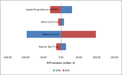
Figure 2: Sensitivity Analysis for case 62.5 MMSCFD
It can be concluded that the project is economically feasible and the variable that impact the most the economics of the project is the gasoline price.
6.0. Recommendations
- We recommend considering the fractional conversions for C2-C11 compounds in reactor 1 to have a better picture of STG+ with its close loop process.
- A thorough composition analysis for gasoline in the fourth reactor gives more realistic results.
- There is much scope to extend our work by adding gasoline treatment and distillation column (instead of flash drum for more efficient separation) with proper chemical reactions and stoichiometric fractional conversions and kinetics to improve the market value of our product.
- There is possibility for considering more components in the feed gas till C5-C6.
- In our model, due to lack of data, we focused on chemical reactions and stoichiometric fractional conversions. There is scope for more efficient designing by working on catalyst cycle life.
7.0. Conclusion
The 21st century is witnessing the establishment of a new global business based on natural gas processing. As a consequence, the gas-to-liquids (GTL) industry is becoming increasingly important as it is getting more difficult to find and extract new oil reserves as well as the presence of more environmental restraints. This is why we decided to apply the new STG+ process technology in our project to demonstrate its efficiency in the conversion of methane to gasoline. As previously stated, we decided to differ from the previous group process, mainly because its technology is old and their product is diesel as opposed to STG+ process which is a novel technology and its product being gasoline, which is more demanded in Canada. We chose to do the simulation of a small scale GTL plant that processes 10 MMSCFD of methane, producing 672 bbld, which resulted in an economically viable process. The economic indicators showed that, by increasing the production of gasoline, the profit would increase significantly (proven with the case 0f 62.5 MMSCFD). In conclusion, STG+ might be indeed successful and profitable in Alberta if there is a reliable source of natural gas and good market conditions.
8.0. References
- Alberta energy website.http://www.energy.alberta.ca/NaturalGas/1316.asp. Accessed on March 16th, 2017.
- Alberta energy website.http://www.energy.alberta.ca/Electricity/679.asp. Accessed on March 16th, 2017.
- Aspentech Support Technology, Inc.; “Aspen Physical Property System 11.1”; Cambridge, MA, September 2001.
- Choudhary V. R., Rajput A. M., Prabhakar B; “Low temperature oxidative conversion of methane to syngas over NiO-CaO catalyst”; Chemical Engineering Division; National Chemical Laboratory, India, May 1992.
- Haro P, Trippe F, Stahl R, Henrich E. “Bio-syngas to gasoline and olefins via DME: A comprehensive Techno-economic assessment”; Apple Energy; 2013; volume 108; page no.: 54-65.
- Heng H.C., Idrus. S; “The future of gas to liquids as a gas monetization option”; Journal of Natural Gas Chemistry 13, 2004; pages 63-70.
- http://www.albertagasprices.com/index.aspx?fuel=C . Accessed on March 16th, 2017.
- Kasaie M., Sohrabi M.; “Kinetic Study on Methanol Dehydration to Dimethyl Ether Applying Clinoptilolite Zeolite as the Reaction Catalyst”; Chemical Engineering Department, Amirkabir University of Technology, Tehran, Iran, January 2010.
- Keil, Frerich J.; “Methanol-to-hydrocarbons: process technology”; Department of Chemical Engineering, Technical University of Hamburg-Harburg, Hamburg, Germany, July 1998; page 49.
- Larminie, James, Dicks, Andrew; “Fuel Cell Systems Explained”; West Sussex, U.K.: John Wiley & Sons; 2000.
- Lebarbier V. M., Dagle R. A., Kovarik L., Adarme J. A. L., King D. L., Palo D. R.; “Synthesis of methanol and dimethyl ether from syngas over Pd/ZnO/Al2O3 catalysts”; Richland, USA, June 2012.
- Mbodji M., Commenge J.M., Falk L., Di Marco, Rossignol F., Prost L., Valentin S., Joly R., Del-Gallo P. “Steam methane reforming reaction process intensification by using a milli structured reactor: Experimental setup and model validation for global kinetic reaction rate estimation”, Chemical Engineering Journal, vol. 207-208, pages 871-884.
- Primus Green Energy website (http://primusge.wpengine.com/press-room/white-papers/), Accessed in March 2017.
- Shell Global Website (http://www.shell.com/energy-and-innovation/natural-gas/gas-to-liquids.htm), Accessed March 05, 2017.
- Wood, David A., Nwaoha C., Towler, Brian F; “Gas-to-liquids (GTL): A review of an industry offering several routes for monetizing natural gas”; Journal of Natural Gas Science and Engineering, Volume 9, November 2012.
- Yang, Christopher; & Ogden, Joan M. (2005).”Analyzing Natural Gas Based Hydrogen Infrastructure – Optimizing Transitions from Distributed to Centralized H2 Production”; Institute of Transportation Studies; UC Davis.
9.0. Appendix
|
Component in Aspen Plus® |
Component name |
Formula |
Mass yield |
|
METHANE |
Methane |
CH4 |
—- |
|
METHANOL |
Methanol |
CH4O |
—- |
|
CO |
Carbon monoxide |
CO |
—- |
|
CO2 |
Carbon dioxide |
CO2 |
—- |
|
H2O |
Water |
H2O |
—- |
|
ETHER |
Dimethyl ether |
C2H6O |
—- |
|
H2 |
Hydrogen |
H2 |
—- |
|
OCTANE |
n-Octane |
C8H18 |
3.582 |
|
HEXANE |
n-Hexane |
C6H14 |
2.702 |
|
HEPTANE |
n-Heptane |
C7H16 |
3.142 |
|
NONANE |
n-Nonane |
C9H20 |
4.022 |
|
DECANE |
n-Decane |
C10H22 |
4.462 |
|
N-C11 |
n-Undecane |
C11H24 |
24.602 |
|
N-C5 |
n-Pentane |
C5H12 |
36.078 |
|
OXYGEN |
Oxygen |
O2 |
47.549 |
|
ETHANE |
Ethane |
C2H6 |
4.901 |
|
PROPANE |
Propane |
C3H8 |
45.691 |
|
N-BUTANE |
n-Butane |
C4H10 |
69.321 |
|
ISOC4 |
Isobutane |
C4H10 |
101.615 |
|
ISOC5 |
2-Methyl-butane |
C5H12 |
75.269 |
|
ISOC6 |
2-Methyl-pentane |
C6H14 |
34.921 |
|
ISOC7 |
2,2-Dimethylpentane |
C7H16 |
3.137 |
|
ISOC8 |
2,2-Dimethylhexane |
C8H18 |
1.690 |
|
ISOC9 |
2-Methyloctane |
C9H20 |
0.491 |
|
ISOC10 |
2-Methylnonane |
C10H22 |
37.092 |
|
AROMC6 |
Benzene |
C6H6 |
4.024 |
|
AROMC7 |
o-Xylene |
C8H1 |
Cite This Work
To export a reference to this article please select a referencing stye below:
Related Services
View all


DMCA / Removal Request
If you are the original writer of this essay and no longer wish to have your work published on UKEssays.com then please click the following link to email our support team:
Request essay removal