Electrostatic Ion Thrusters
| ✅ Paper Type: Free Essay | ✅ Subject: Engineering |
| ✅ Wordcount: 823 words | ✅ Published: 30 Aug 2017 |
Abstract
The ion thrusters belong to the electric propulsion category and are used by modern spacecraft either to maintain their position relative to the Earth or to complete deep space missions. Their main characteristic is the high specific impulse which involves an efficient use of the propellant, a mandatory requirement for space activities where weight is the main restriction. The thrust is generated by the acceleration of ionised gas at very high velocities. The mechanism used to achieve the acceleration distinguishes these propulsive devices in two main categories: electrostatic and electromagnetic. In the first type, a potential difference accelerates the ions through the Coulomb’s force. In the second type the interaction of the ionised gas with a magnetic field generates the thrust through the Lorentz’s force. This paper focuses on the analysis of the main features and architectures of the electrostatic ion thrusters. In the first part, the reasons why they are used for space applications are explained. Afterwards, the propulsors physic and the working principles are illustrated with considerations on their advantages and limitations. Eventually, an overview of the field of applications and future design innovations is presented.
Keywords: Ion thrusters, Hall thrusters, Feep
Nomenclature
EPElectric Propulsion
ESAEuropean Space Agency
NASANational Aeronautics and Space Administration
JAXAJapan Aerospace Exploration Agency
GEOGeostationary Orbit
LEOlow Earth Orbit
STPStationary Plasma Thruster
Electrostatic ion thrusters are a major area of interest within the field of space applications. Thanks to the constant heightened of electrical power available in modern spacecraft the last two decades have seen a growing proliferation of this technology. The concept of electric propulsion has been theorized for the first time by Robert H. Goddard in 1906[1] and Herman Oberth in 1929[2] but it was not until 1948 that the research efforts on ion thrusters implementation on a spacecraft began. A considerable contribution was given by the work of Ernst Stuhlinger[1]. Early experimental tests started during the 50’s and leaded to the first successful space test in 1964 with the SERT-1[3]. With the end of the Cold War and the “Space Race” the interest in these devices diminished but just for a short period. Today in fact ion thrusters are essential for a wide range of space missions. In this paper, after a brief explanation of the importance of high impulse thrusters for space applications, the three main architectures of electrostatic ion thrusters are presented. For each category the paper will look into the working principles, evolution over the years, applications in space mission and future development of the technology.
The essential reason of the development of the ion thruster for space applications is the extremely high efficiency in the utilisation of propellant mass and the corresponding reduction of the launch costs, a critical parameter for the mission feasibility. Moreover this technology permits to performs deep-space missions otherwise inaccessible to conventional chemical rockets[4]. The reason lies in the Tsiolkovsky’s equation which can be derived from the Newton’s law of momentum conservation:

Where  and
and  are the final and the initial spacecraft mass respectively,
  is the velocity change and
  is the exhaust velocity. The equations shows that must be comparable to to have a significant fraction of final mass. Thrusters that provide a large propellant exhaust velocity compared to the mission will have a propellant mass that is only a small fraction of the initial spacecraft wet mass. Space mission are classified by the amount of velocity change needed for the orbital maneuvers, planetary mission for example requires velocity above 10 km/s[4].
Table 1:Characteristic velocity increments
|
Mission |
|
|
1 year station keeping |
10 |
|
LEO – GEO |
3.5 |
|
Earth – Mars (return) |
14 |
|
Earth – Venus (return) |
16 |
|
Earth – Jupiter (return) |
64 |
|
Earth – Alpha Centaury (return) |
30000 |
The exhaust velocity is directly proportional to the specific impulse, which can be seen as a measure of the propellant acceleration efficiency. The formulation is:

where  in the mass flow and
  the sea-level gravitational acceleration. Typical values of different propulsive systems are listed in table 2. It can be seen that the necessary velocity augmentation is much larger than the typical chemical rocket exhaust velocity, for this reason they are not suitable for this kind of missions. The latter is restricted by the intrinsic energy of the propellant, thermal limitations of the materials and frozen flow losses[4]. For electric thrusters the propellant and the energy source are independent and the specific impulse depends only on the energy deposed into the plasma[5]. Another key strength of ion thrusters is the high thrust efficiency:

where  is the available electric power and
  is the thrust. The equation shows that defined a large specific impulse leads to a very low thrust level which is a typical characteristic of ion engines. As a consequence this kind of thrusters requires a large amount of propulsion time, actually the opposite of what happens with chemical propulsion, characterised by high thrust levels over a short time.
Table 2: Representative specific impulse and thrust levels of different propulsive systems [2]
|
Propulsive system |
|
Thrust [N] |
|
Liquid monopropellant |
200 – 250 |
0.01 – 100 |
|
Liquid bipropellant |
300 – 450 |
0.01 – 10^7 |
|
Solid propellant |
200 – 300 |
1 – 10^6 |
|
Hybrid propellant |
250 – 350 |
1 – 10^6 |
|
Ion Thrusters |
2000 – 5000 |
<0.2 |
|
Hall Thrusters |
1500 – 2500 |
<2 |
|
Feep Thrusters |
5000 |
0.001 |
 [s]
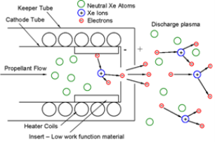
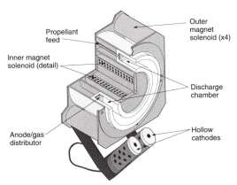
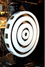
[s]Electrostatic ion engines overcomes the limitations on the attainable exhaust speeds of conventional chemical rockets by the acceleration of the propellant through an electrostatic field. They can be divided into three main categories: Gridded Ion Thrusters, Hall Effect Thrusters and Field-Emission Electric Propulsion. In each of those the same main functions are performed: generation of the plasma, ions acceleration and ions neutralization.
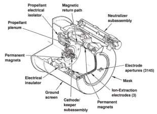
This configuration is the most fully developed and studied concept of electric propulsion [4]. The standard design comprises a metal ionisation chamber surrounded by magnets and three grids at the exit position. ??
Acc elettroni
4.1 Ionisation and extraction
Plasma is a ionised gas where approximately an equal number of positively charged protons and negatively charged electrons coexists[6]. The generation of positive particles requires an energy equivalent to the first ionization energy of the propellant. This amount of energy has an impact on the maximum attainable efficiency of the thruster that according to[5] can be written as:
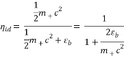
where  is the ionisation energy and
  is the ion mass. The equation displays that the higher the ion mass and exit velocity (hence specific impulse) the higher the efficiency while decreases it. For this reason propellants with a low specific ionisation energy (alkali metals and noble gases) are preferred. The lower limit for the utilisation on these type of thrusters is 2000 s.

Modern ion thrusters uses Xenon as a propellant since it has a large atomic weight and it easy to store because it is an inert gas, although Mercury and Caesium would be more performant propellants since their mass is much larger and the ionisation energy slightly greater, the higher toxicity prevents their use in experimental tests.
|
Propellant |
Ionisation potential [eV] |
Atomic mass [AMU] |
|
Caesium |
3.9 |
132.9 |
|
Mercury |
10.4 |
200.6 |
|
Xenon |
12.8 |
131.3 |
|
Krypton |
14.0 |
83.8 |
|
Hydrogen |
15.4 |
2.0 |
There are two mechanisms to create the plasma: the electron-bombardment and the relatively recent frequency excitation. In the first type electrons emitted from a thermionic or a hollow cathode collide with the propellant gas and generates positive ions. The electrons tend to reach the anode but the presence of an axial magnetic field generated by the magnets outside of the chamber causes a spiral path that improves their confinement and the ionisation efficiency. When an electron ionises an atom its energy decreases and when it drop below a certain level the magnetic field is not able to confine it anymore and it is extracted by the anode.
In the second type the ionisation chamber is surrounded by a coil that induces an axial electro-magnetic field that ionises the gas. This method has some advantages such as the elimination of the cathode which improve the thruster life and a larger range of mass flow variation [7].

The number of ions created is equal to the number of electrons captured by the anode and an equilibrium condition is established. The plasma potential is slightly higher than the one of first grid, as a consequence the generated ions are attracted towards the exit of the chamber. In this region a sheet of the debaey length causes a natural curvature of the electric field and permits the extraction of the ions.
Sheets debay
4.2 Acceleration
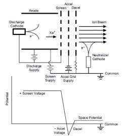
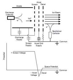
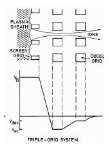
The extraction of the ions from the ionisation chamber and the acceleration are performed by an electric field applied by three perforated grids. The first one acts as a screen while the second and the third accelerate and decelerate the gas respectively. The design of the grids is crucial and is based on a trade-off among performance, life and size. The grid holes diameter is defined by conflicting targets, it must be enough small to retain the unionised gas but maximised to provide an high grid transparency to extract the maximum possible number of positive ions[5].
An high potential difference is applied between the first and the second grid which accelerates the ions:

where  and are the ion charge and mass respectively and is the potential difference. The potential of the intermediate grid is negative in order to avoid the back-streaming of the electrons from the neutralizer cathode.
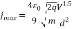
The presence of positive particles only, during the acceleration, leads to an essential upper limit in the ion current density that can by provided and hence to the thrust density (N/m^2) of this devices with adverse consequences on their size[7]. The limit is dictate by the Child-Langmuir law[8]:
that involves a thrust per unit of area of:
 where A is the cross area of the jet, d is the distance between the grids and
  is the electric constant. The formula demonstrates that to have compact device heavy ions and an high voltage are needed while the gap between the grids must be very small and this constitutes a thermal, electrical and structural challenge. Adopting Xenon and the maximum electric potential difference with nowadays technology level (typical value is 1000 Volt) the value
 which is very low. The exhaust speed achieved in this case, and hence the specific impulse, is excessively high considering the actual space mission requirements. Since just lowering the potential difference would reduce the already small value of thrust density a third deceleration grid is added[1]. Placing the acceleration grid at a negative potential the problem of the excessive velocity is solved without compromising the thrust density. The value of the required specific impulse determines the value of the third grid potential[5].
The single charge nature of the beam causes the repulsion between the accelerated ions which tend to diverge from the axial direction. Since the repulsion force is proportional to the beam diameter the latter is subdivided into small portions with order of magnitude equals to the grids distance. Since the electric field generated by the first grid is convergent the grid can be designed in such a way that particles trajectory became axial due to the repulsive force inside the beam.
The grid geometry and the ions trajectory have a crucial roles in determining the thruster life, for this reason they are made of heavy metals such as Molybdenum, Graphite composites have been recently introduced[7]. Even though the grid are accurately designed, a secondary current of low energy ions hits the accelerator grid causing erosion. This current is caused by the Charge-Exchange Ionisation: some neutral atoms of propellant escaping from the ionisation chamber are struck by beam ions and a charge exchange happens[5]. The resultant low energy ions are accelerated towards the intermediate grid with enough energy to consume it over a long period. This process leads to a distortion of the grid holes that increases the damage until a structural failure of the grid occurs or the back streaming of electrons is not prevented anymore.
4.3 Neutralisation
 If the positive charged ions beam exiting from the thruster is not neutralised the thruster acquires a negative potential and causes the ions back-streaming. The neutralisation is achieved by the emission of a negative current by an hollow cathode positioned outside of the ions streams.
Since the potential difference in this case is very low (electrons don’t need to be accelerated) and the distance is an order of magnitude larger than the grid gap, the Child’s law prevents the emission of a pure electrons current. The solution is the utilisation of a plasma bridge, a global neutral plasma with an electrons current inside. The hollow cathode is constituted by a tube of refractory materials and an orifice plate at the downstream end[9]. Inside the tube an insert made of tungsten is impregnated with a low work-function metal. The cathode is wrapped by an heater that allows electrons emission through thermionic effect when temperature reaches 1000°C[9]. Xenon is fed into the tube and electrons emitted from the insert are extracted by a keeper electrode downstream of the orifice.
4.4 Evolution of the technology and future development
The first ion engine flight was the demonstrative mission “Space Electric Rocket Test” (SERT 1) in 1964[3], followed in 1970 by the SERT 2 whose two mercury thrusters achieved 2000 and 3700 hours of operations respectively providing 300 restarts[10].
 The first use of gridded ion thrusters adopted for station keeping for commercial applications has been the XIPS-13 in 1997 for the PAS-5 (PanAmSat-5) communications satellite[5]. The subsequent generation of gridded ion engine, NSTAR, was developed by NASA JPL and Boeing. This thruster equipped the Deep Space 1 in 1998[11], a demonstration spacecraft that reached an asteroid and a comet. It provided 16000 hours of operation during the mission and over 40,000 hours of life testing[5]. Hundreds of papers have been published on its design and performance.
In 1999 an evolution of the XIPS-13, the XIPS-25, was first lunched on a Boeing 702 Satellite[12]. This second generation is capable of providing orbit raising other than station keeping and momentum control. To date these thruster have been used for station keeping on Boeing 702 class satellites for more than 10 years, and 68 are currently operating in orbit on 17 spacecraft[5]. The next model used for station keeping was lunched on the telecom satellite Artemis in 2001 by the ESA. It used two T5 and two RIT thruster developed by Astrium[13]. The satellite reached a GEO orbit thanks to the ion thrusters used as a primary propulsion for recovery the chemical stage failure.
In 2003 JAXA lunched the Hayabusa mission which equipped with four ion thrusters collected samples from an asteroid and returned to Earth in 2010[14]. Later in 2007 the Dawn[ mission of NASA was lunched to study two protoplanets in the asteroids belts, Vesta and Ceres, it has been the first time that a spacecraft orbited around two different solar system bodies, it would have been impossible without ion engines[15]. In 2009 the Gravity Field and Steady-State Ocean Circulation Explorer (GOCE) mission was lunched to study the variations of Earth gravitational field[16]. The key component of the mission were two ion thrusters for drag compensation. A new challenging mission named Bepi-Colombo is planned for October 2018 by a collaboration between ESA And JAXA[17]. The aim is the exploration of Mercury and will use four QinetiQ T6 ion thrusters. Another gridded ion thruster available in near future will be the NASA Evolutionary Xenon Thruster (NEXT)[17], Glenn Research Center manufactured the test engine’s core ionization chamber, and Aerojet Rocketdyne designed and built the ion acceleration assembly[18]. A long duration test(LDT) was initiated in 2005 and was voluntarily terminated in 2014 after more than 50000 hours of operation and almost 1 ton of Xenon consumed. Post-test inspection highlighted the readiness of the thruster for space use[19][20]. It has been proposed for several future missions[21]. The first two flight units will be available in early 2019.
|
Name |
Power [Kw] |
|
T [mN] |
|
SERT 1 |
1.4 |
4900 |
28 |
|
XIPS 13 |
0.33 |
2570 |
18 |
|
NSTAR |
0.5-2.3 |
3100 |
20-95 |
|
XIPS 25 |
4.5 |
3800 |
165 |
|
RIT |
4.3 |
3-5000 |
150 |
|
T5 |
0.27-0.65 |
3-3500 |
10-25 |
|
T6 |
5.2 |
3500 |
40-200 |
|
NEXT |
0.5-7 |
4200 |
237 |
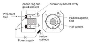
The Hall thrusters are direct competitors of the gridded ion thrusters, even if they have a lower efficiency and specific impulse the thrust density is many times greater since both ions end electrons are accelerated and the Child’s law is not a limit. The system is based on a fundamental effect discovered in 1879 by Edwin H. Hall[22], he showed that in presence of a perpendicular electric and magnetic field an electric current flows perpendicular to both. This phenomenon is exploited for the ionisation and the acceleration of the propellant.
5.1 Working Principles
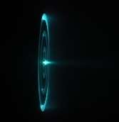
 The ionisation chamber is axisymmetric, enclosed in two concentric cylinders. A radial magnetic field is applied through permanent magnets or solenoids, at the entrance of the chamber is situated a metallic anode from which the propellant is injected. At the cylinder end an hollow cathode emits an electrons beam that is divided into two parts. About 60-80% of the electrons are used to neutralise the positive ions ejected from the chamber, the remaining are trapped by the magnetic and the electric fields at the chamber exit and constitute a virtual plasma cathode[7]. The direct flows of the electrons towards the anode is prevented by the Hall effect which causes a spiral trajectory of the electrons.
The propellant unleashed at the chamber entrance moves towards the electrons region and is ionised. Then the resultant electric field accelerates the ions. The long residence time of the electrons in the annular chamber, due to the magnetic confinement, makes the ionisation very efficient. Even if the magnetic field is determinant for the thruster operation the acceleration is achieved by a stationary electric force. The magnetic field that confines the electrons, which peaks at the exit, affects the ions trajectory causing a disturbance tangential torque that must be compensated and an high beam divergence angle of about 40° that reduces the thrust efficiency and may cause electrostatic charging and interference to the satellite communications.
The ionisation is much more efficient than in the gridded ion thrusters thanks to the lower ionisation energy requested and permits to achieve satisfactory efficiency 50-60% even with a relative low specific impulse. The considerable complexity of the plasma dynamic due to the presence if the magnetic and the electric field within the thruster causes fluctuations in the electron density that could cause severe damages, for this reason the electric potential is limited to 350 Volts.
5.2 SPT and TAL variants
On the basis of the different materials that constitutes the cylinder wall in contact with the plasma Hall thrusters are divided into Stationary Plasma Thrusters (SPT), that are characterised by insulating walls made of boron nitride and silica compound (BN-SiO2), and Thruster Anode Layer (TAL) which have a conductive one[23]. Since the walls are continuously hit by some electrons and consecutively emits other electrons because of the secondary electron emission (SEE) effect, if the wall are metallic the resultant quantity of electrons is larger, the electric field is more intense and the potential drop occurs in a shorter distance. The result is more compact architecture with higher thrust density. The power loss are also related to life are strongly influenced by wall interactions. For SPT thrusters a significant amount of their power is lost on the dielectric channel walls due to electron bombardment. The metallic walls in TAL thrusters gather a smaller electron current since they have the same potential of the cathode which rejects the electrons and they have a small exposed area to the plasma, which limits the amount of ion and power lost to these surfaces. On the other hand the shorter chamber raises the intensity of the discharge current on the anode because the magnetic confinement is less effective [7].
5.3 Evolution of the technology and future development
The first Hall-Effect thruster to operate in space was the SPT-50 aboard the Soviet Meteor spacecraft in 1971 and was mainly used for satellite stabilization. Starting from that year more then 140 Hall thruster have been used in space[24]. Subsequently Hall engine of different power and size were developed with the introduction of the SPT-70 and SPT-100 in 1982. With their introduction in the west after the fall of the Berlin Wall in 1989 lot of research have been carried out by United States, France, Italy and Japan. The first US mission that adopted this technology was the demonstrator STEX spacecraft using D-55 TAL Hall Thrusters manufactured in Russia[25]. In 2004 the ESA’s satellite SMART-1 adopted the Snecma PPS-1350-G, with a design similar to the SPT-100, to reach the lunar orbit from GTO[26]. The mission finished in 2006 with a controlled collision on the Moon’s surface. The probe covered more than 100 million kilometres, consuming just 82 kg of propellant.
The joint venture between the Busek Company and Aerojet Rocketdyne leads to the development of the BTP-4000 designed for US military spacecraft as well as commercial satellites. In 2000 an agreement between Aerojet and Lockheed Martin Space System Company (LMSSC) developed the Hall Thruster Propulsion System (HTPS) for the next generation LMSSC geosynchronous spacecraft, this program adopted the BPT-4000 because of the ability to operate in a large range of powers and thrust modes allowing both station keeping and orbit raise[18]. Flight test qualifications and improvements lead to the discovery of the magnetic shielding phenomenon[27]. The achievement of a particular magnetic topology that essentially blocked the chamber wall erosion after 6000 hours, the developed erosion model enabled the possibility to predict andextent the engine lifetime. This thruster, used on the Advanced Extremely High Frequency (AEHF) communications satellites constitutes the currently most powerful Hall engine in operation.
In 2009 AR and Lockheed Martin developed the XR-12, the first Hall thruster in the 10kW class, it was intended for the US Air Force’s TSAT constellation but after the cancellation of the program its use for future missions have been studied by NASA. In the recent years high power and thrust Hall engine have been investigated thanks to the increasing of the available spacecraft power. The consequent increase of thrust reduces the amount of time for the mission and permits a larger payload.
In Europe Snecma developed the PPS-20k for the HiPER Project, an European project to study innovative electric propulsion technologies for future space transportation and exploration.
In 2010 NASA promoted the Human Exploration Framework Team (HEFT) to investigate new technologies for a future human space exploration and high power Hall thrusters, thanks to the high power processing capabilities and extensive range of thrust levels, were chosen as a possible technology. The NASA-457Mv2 50-kW class, whose development started in 2004, has been tested during 2011 with satisfactory results. This model can be a potential point of start for future NASA exploration missions.
Another step forward has been made with the development of the X3, a 100-kW class three-channel nested Hall thruster, designed by the Plasmadynamics and Electric Propulsion Laboratory (PEPL) at the University of Michigan, in collaboration with NASA and the Air Force Office of Scientific Research. Its performances up to 30 kW have been recently successfully tested and further measurements in order to analyse the complete operating envelopment up to 200 kW will be effectuated in the near future.


|
Name |
Power [Kw] |
|
Cite This Work
To export a reference to this article please select a referencing stye below:
Related Services
View all


DMCA / Removal Request
If you are the original writer of this essay and no longer wish to have your work published on UKEssays.com then please click the following link to email our support team:
Request essay removal