Design of Interventional Biomedical Devices
| ✅ Paper Type: Free Essay | ✅ Subject: Engineering |
| ✅ Wordcount: 3894 words | ✅ Published: 30 Aug 2017 |
1. Neurovascular Catheters and Engineering Design
1. Case Study 1.
The following catheter found in the ”cathlabdigest” written by Gill Laroya discusses the advancement of the design of interventional biomedical devices from an engineering perspective and how engineers enhance the design of catheters to prevent problems such as kink. The article discusses areas such as the history of biomedical devices, the materials involved, design challenges and the interface. It discusses a specific example in terms of catheters and their use. If a catheter must travel a long distance within the neurovascular anatomy, the engineer designing the product might decide to incorporate a shaft support component, such as a stainless steel braid in order to enhance the micro catheters kink resistance. The down side of incorporating the stainless steel braid is its ability to travel within tight sections and irregular shaped bends within the neurovascular system. In order to solve this problem a stainless steel coil support is added to the distal end of the catheter, the addition of the coil support enhances lateral flexibility and adding hoop strength to even better the kink resistance of the micro catheter. Also, the engineer can add a lubricous hydrophilic coating to the catheter to improve axial and rotational handling of the device and reduce trauma on the walls of the veins and arteries. The study shows us how we can design micro catheters to prevent problems such as kink occurring. Cathlabdigest.com. (2016). The Design of Interventional Devices: An Engineer’s Perspective | Cath Lab Digest.
2. Neurovascular Catheter Design
The following article was posted in Medical Tubing Types by Shana Leonard on December 12, 2014. Form the article it is predicted that by 2020 the neurovascular market will reach $600 million, according to iData Research. A key factor contributing to the growth of this sector is down to the various advancements of the biomedical device. The design goal for minimally invasive surgical devices is to strive towards engineering the smallest possible outside diameter for a micro catheter device without compromising any of the performance characteristics. Designing neurovascular catheters to meet these constraints must take into account the intricate neurovascular anatomy. Mddionline.com. (2016). Key Considerations for Designing Neurovascular Microcatheters | MDDI Medical Device and Diagnostic Industry News Products and Suppliers.
According to Steven W. Berhow, president of Rogers, MN-based Biomerics Advanced Catheter, he believes that upon designing neurovascular catheters they must contain the following traits;
- Good torque within the shaft from the proximal to distal end.
- Flexibility in the distal portion of the catheter.
- Kink Resistance.
- Visibility under fluoroscopy.
- Low Stretch.
- High Pressure.
- Good guidewire movement.
These 7 traits stand as basic constraints when it comes to designing intricate, complicated neurovascular minimally invasive devices.
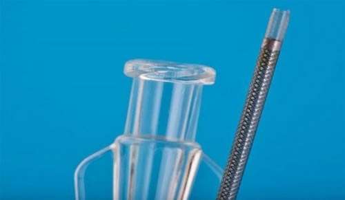
Figure 2. Neurovascular Catheter Design.
Mddionline.com. (2016). Key Considerations for Designing Neurovascular Microcatheters | MDDI Medical Device and Diagnostic Industry News Products and Suppliers.
3. Advanced Catheters
The first thing you need to know is what an advanced catheter is. So according to Bill Alexander, Director of Business Development at Biomerics Advanced Catheter, ‘an advanced catheter is a minimally invasive medical device that typically consists of a thin walled, braid reinforced tube or shaft with multiple durometers.’ An advanced catheter has the ability to navigate through the neurovascular anatomy and deliver implants and devices such as coils, heart stents etc.
The difference between advanced catheters and traditional catheters can be mainly seen when it comes to manufacturing the product. A little error in the materials used in an advanced catheter can lead to larger errors as the specific wall thickness requirement of an advance catheter are very strict to ensure optimal performance. Characteristics such as pushability, trackability, torqueability and kink resistance are crucial for the advanced catheter design. Traditional catheters and advanced catheters are not mutually exclusive and can be used to benefit each other and improve patient surgical results. (2016). Advanced catheters – What you need to know about this growing medical device market.
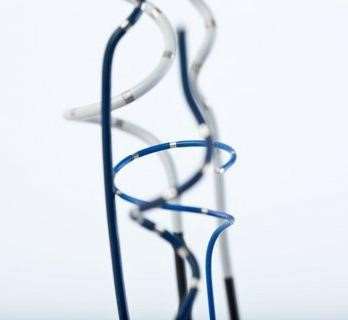
Figure 3 Advanced Catheters and Traditional Catheters.
(2016). Advanced catheters – What you need to know about this growing medical device market.
Advanced catheters have the ability to incorporate new technologies and have a more complex design than traditional catheters.
2. Human Neurovascular and Cardiovascular Anatomy
1. Cardiovascular System
The cardiovascular system consists of the heart and blood vessels along with blood itself. It transports oxygen, nutrients, hormones and more and is powered by the heart. The heart consists of 2 circulatory loops, the pulmonary circulation loop and the systematic circulation loop. The pulmonary circulation transports deoxygenated blood from the right atrium and ventricle to the lungs. The systematic circulation carries oxygenated blood from the left atrium and left ventricle to all around the body. The cardiovascular system consists of blood vessels, coronary circulation (hearts own set of blood vessels), hepatic portal circulation (veins of stomach and intestines) and the blood itself (red blood cells, white blood cells, platelets and plasma). An understanding of the complex network and its physical structures are important when designing non-invasive medical devices. System, C. (2016). Cardiovascular System. InnerBody.

Figure 4 Cardiovascular System.
Slideshare.net. (2016). Circulatory system PowerPoint
Blood vessels are the road network by which blood transports around the body and returns back to the heart again. This intricate tiny transportation system of blood vessels has a major part to play when engineering advanced catheters and ensuring problems such as kinking don’t occur.
2. Structure and Functions of Blood Vessels
Blood vessels consist of arteries and veins. Arteries bring blood away from the heart. As the arteries are brought away from the heart they eventually become smaller and are broken down to the smallest arteries called arterioles which further branch into capillaries where gases and nutrients are excreted or exchanged. Veins have a larger structure and bring blood back to the heart again. As can be seen below in figure 4, the cardiovascular circuit can be seen where two main circulatory systems occur. The pulmonary circulatory system and systematic circulatory system. Each providing their own different structural differences that engineers must take into account when designing minimally invasive medical devices. Philschatz.com. (2016). Structure and Function of Blood Vessels · Anatomy and Physiology.
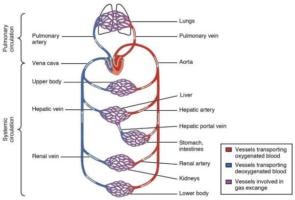
Figure 5 Structure of Blood Vessels. ] Philschatz.com. (2016).
The structure of blood vessels can be seen below. The artery and the veins vary in thickness as can be seen from the micrograph in figure 6. From figure 5, it can be seen that Arteries have a thicker Tunica media than Veins but veins have a larger tunica externa than arteries.
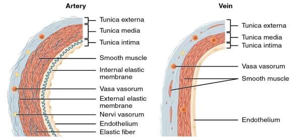
Figure 6 Arteries vs Veins Structural differences. Philschatz.com. (2016).

Figure 7 Micrograph showing the relevant difference in thickness. Philschatz.com. (2016).
As can be seen in figure 6 and 5, vein walls are considerably thinner than Artery walls meaning veins withstand a much lower pressure of blood passing through them.
Table 1 Appearance of Arteries and Veins. Philschatz.com. (2016).
|
Arteries |
Veins |
||
|
General Appearance |
Thick walls, small lumen Rounded appearance |
Thin walls, large lumen Flattened appearance |
|
|
Conor Patrick Goold, DME4. |
7 |
||
3. Shapes of Catheters in the Neurovascular Anatomy
1. Guide Catheters and shapes in the Neurovascular system.
The following is an example of a Stryker neurovascular catheter called the DAC catheter. From figure 8, it can be seen that the DAC catheter accesses the distal neurovasculature. It achieves this by providing enhanced stability through a braided shaft and this in turn also provides resistance to ovulation. Preventing shapes such as ”snaking” and reducing friction against the blood vessel walls. Stryker.com. (2016). Neurovascular Intervention – DAC™ Catheter: Stryker.
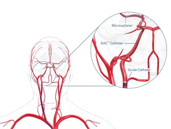
Figure 8 Catheters, Shapes and Uses. Stryker.com. (2016). Neurovascular Intervention – DAC™ Catheter: Stryker.
2. Neurovascular Catheters in the Brain.
The following images are obtained through a technique that requires the use of a minimally invasive advanced neurovascular catheter. What these images do is they give a visual understanding of the intricate nature in which the catheters must travel within the cardio vascular system. To do this the catheter is guided under x-ray guidance through neurovascular and cardiovascular system. The catheter for this procedure is usually brought to a blood vessel located in the neck and a non-ionic x-ray contrast agent is injected into the blood vessels which then in turn travels through to the brain. Prior to this procedure the catheter is then removed through the groin and the bleeding is stopped through direct manual compression or by using a vascular closure device. Neuroangio.org. (2016). Introductory Brain Angiography | neuroangio.org.

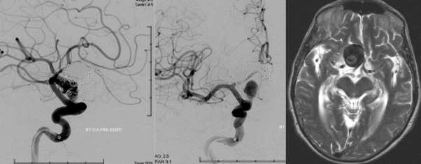
Figure 9 ICA Internal Carotid Artery. Neuroangio.org. (2016). Introductory Brain Angiography | neuroangio.org.
In order to reach such distances in the neurovascular system, many advanced catheters are used to travel so far. The deployment of a large support catheter through the groin goes first and then a variation of other smaller catheters are deployed through the larger catheter in order to reach the required location and deploy medical devices such as coils and stents.
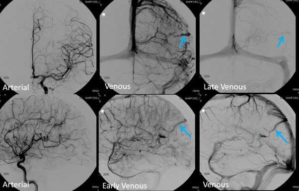
Figure 10. CT scan of Brain. Neuroangio.org. (2016). Introductory Brain Angiography | neuroangio.org.
3. Neurovascular Catheters in the heart.
Figure 11 shows the placement of a pacemaker into the heart by the deployment from a minimally invasive advanced catheter. The catheter enters the body through the collar bone on the left hand side of the heart and enters through the veins to place an electronic or mechanical pacemaker into the heart to overcome heart problems such as tachyarrhythmias, which occurs when your heart beats too fast or bradyarrhythmias, which occurs when your heart beats too slow. System, C. (2016). Cardiovascular System.
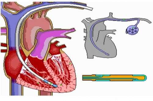
Figure 11 Advanced Catheters in the Heart. System, C. (2016). Cardiovascular System.
From figure 11, the ”C” shaped position of the catheter can be seen. A number of issues can occur from an engineering perspective when a catheter must bend into the shape of a ”C”. Kinking can occur at the maximum area of stress and strain. Engineers must design their advanced catheters in order to prevent kink from occurring and so a reinforcement braid is usually added to increase the hoop stresses of the catheter and the addition of this braid also provides better torqueability and pushability of the medical delivery device to allow it to bend to the required positions to deploy a pacemaker in the heart.
4. Research into Existing Test Methods
1. Simple existing Test methods
The following is the most basic of test methods implemented by physicians when no Standard test method is available and time is of the essence. This method was applied when surgeons were experiences kinking in catheters when deployed into patients. In order to predetermine kink from happening the physicians used a simple bending technique to test for the kinking limit of catheters. If the catheter kinked, the unit was rendered useless, if not it was determined safe to use. This method is clearly not an optimal solution so further investigation into the kinking limit of catheters had to be researched and developed. Beamer, J. and French, G. (2016). A simple method for testing for the kinking epidural catheter.
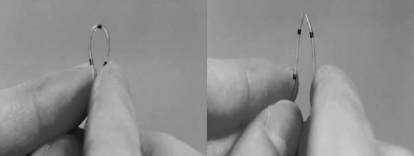
Figure 12 Simple Test Method – No kink LHS and Kinked RHS. Beamer, J. and French, G. (2016). A simple method for testing for the kinking epidural catheter.
1.1 Simple existing test methods
The catheter bends around the pin, having a predetermined diameter, D. The diameter can range from a number of different values, 5mm – 50mm. The catheter is bent around the template and contacts the template at 2 tangential locations, to generate a curve and predetermine L = D.
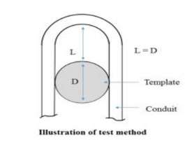
Figure 13 Kink resistance Test Method. Anon, (2016).
2. Guidance for Industry and FDA Staff – Non-Clinical Engineering Tests and Recommended Labelling for Intravascular Stents and Associated Delivery Systems
The following FDA guidelines outline the standards to abide by when dealing with stents and associated delivery systems. It details how the content and format of test data should be summarised in a report as well as detailing the test reports and test protocol procedures to carry out. For this test method, a review of the non-clinical engineering section was undertaken focusing on the section B (Stent Dimensions and Functional attributes) of the non-clinical engineering test, part 16. Part 16 gave FDA guidelines in kink resistance. The significance of outlining FDA guidelines for stents which are delivered by advanced catheters, it to prevent kink occurring when the normal body is in motion such as an elbow joint flexing and to ensure that no deformation to the stent occurs. This also applied to the stent delivery system when the physician deploying the stent into the human anatomy as the advanced catheter must be engineered to prevent kink from occurring upon deployment.
The recommended outcome to prevent kink from happening, according to the FDA guidance document, is to determine the smallest radius of curvature that the stent can withstand and recover to its original shape and size. The test carried out to determine the smallest radius of curvature must replicate the area to which the stent will be deployed i.e. the femoral arteries. This recommended advice for implementing stents to the human body can be tailored towards the stent delivery systems also i.e. the advanced catheters. Therefore these guidelines will be taken into account when developing a test method to determine the kinking limit of catheters. See appendices for further detail regarding the FDA guidance documents discussed. Fda.gov. (2016). Guidance for Industry and FDA Staff – Non-Clinical Engineering Tests and Recommended Labeling for Intravascular Stents and Associated Delivery Systems.
3. Standards and guidelines
ProtomedLabs provide a list of standards and regulations that relate to flexibility and kink resistance test methods. Information on the state of the art available testing equipment is provided such as the interventional device testing equipment (IDTE) from MSI which will be discussed further in part 4 of this section (MSI – Catheter testing equipment). The ProtomedLabs provide information on flexibility kink resistance regarding applicable standards, related tests and test method descriptions. Applicable standards such as the FDA guidelines discussed in heading 2 above as well as ASTM standard guide for three point bending of balloon expandable vascular stents and stent systems which will be further discussed in section 5 of the literature review. Protomedlabs.com. (2016). Flexibility Kink Resistance – Protomed Labs.
4. MSI – Catheter testing equipment
State of the art interventional device testing equipment (IDTE), compares tests and analyses performance catheters, quantifying the data of each catheter being tested. The PC allows for simple and repeatable tests with instantaneous feedback on design changes of the catheter.
The IDTE was designed taking into account several different standards and test regulations such as ISO standard 25539-1 which covers ”cardiovascular implants – endovascular devices” and ISO 15539 ”Cardiovascular implants Endovascular Prostheses”. The product is the most state of the art catheter testing equipment available right now and differentiates itself from the rest of the market by having the ability to test catheters in extremely realistic and challenging conditions. MSI. (2016). Catheter Testing – MSI.
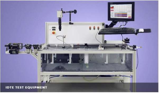
Figure 14. IDTE Test Equipment. MSI. (2016). Catheter Testing – MSI.
The IDTE has a high temperature range with ambient temperatures of 50oC, a water bath with a temperature accuracy of +/- 2oC. It has auxiliary load cells of 100g and distal load cells of 1kg. It has the ability to test track force which is the force needed to advance a catheter, push efficiency which measures the amount of force being measured from the proximal end to the distal end, flexibility, torqueability a measure of the rotational response, retractability a measure of the amount of force required to withdraw a catheter and the crossability which measures the ability of a catheter to cross the abnormal narrowing of a passage in the body. The machine itself weighs 250kg with a height of 1372mm, width of 1194mm and a depth of 940mm. the output data of each tested is outputted onto a computer where numerical or graphical results can be formulated. MSI. (2016). Catheter Testing – MSI.
5. Current Test Methods available to determine Kinking Point
1. ASTM F2606 – Standard guide for three-point bending of balloon expandable vascular stents and stent systems
The three point bending of stent system guidelines provide a test method that can be used to compare the flexibility of different advanced catheters by comparing load deflection curves and by comparison of calculated slopes of the curves.
The test method uses a simple 3 point bending test. The upper single load applier and the two static load supporters as seen below in figure 14 must have a radius of 6.35mm. Another requirement of this test is that both the upper load applier and the two bottom static load supporters must be made of a material with a low friction coefficient so that they do contribute to the results outputted from carrying out this experiment.
This test method can also be carried out in a bath of 37oC, which replicates the ambient body temperature and realistic conditions, if this application is necessary, the fixtures can be made from stainless steel or other materials that will not rust.
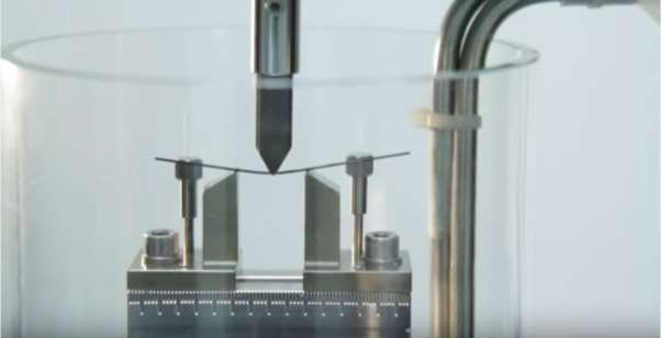
Figure 15 Example of a three point bending test. YouTube. (2017). Catheter Bend Test at Anecto.
This test has many benefits as it can many advanced catheters can be used with this method and it is applicable to many different products. It does not cause damage to the product prior to testing and can test the kinking limit along different material junctions. The test method ASTM F2606 uses a tensile tester to output its results to a computer in numerical or graphical form. Instron.us. (2017). ASTM F2606 Three-Point Bending Balloon Expandable Vascular Stents and Stent Systems – Instron.
3. BS EN 13868 Catheters – test methods for kinking of single lumen catheters and medical tubing
This standard test method looks at the kinking of catheters being used for short term or long term uses. The short term use determines the kinking limit of a catheter being used less in than an hour and the long term is above an hour. The tube is defined as being kinked when the flow meter (Labelled 4 in figure 15 below) is outputting a reading 50% lower than the original reading. The original reading is read when the kink tools (Labelled 7) are either 50mm, 100mm or 200mm apart, depending on the user’s required starting distance. When the kinking tools are being compressed by the tensile tester (Labelled 7) the mass flow rate of the water flowing from the beakers (Labelled 2) will begin to reduce. Once the mass flow rate reduces to 50% of its original the catheter is said to be kinked and the test is complete.
The results are outputted to a computer which gives numerical and graphical results. This test method is very beneficial as it is convenient, safe and fit for purpose. Difficulties may arise when using this test method when it comes to the fittings of the flow meter with the different sized catheters. As all catheters vary in sizes, the universal fitting of the flow meter may be difficult to mate with the distal/proximal ends of the various advanced catheters. See Appendices for more detail regarding BS EN 13868 – kinking of single lumen catheters. European Standard, (2002). Catheters – Test methods for kinking of single lumen catheters and medical tubing. BS EN 13868:2002.
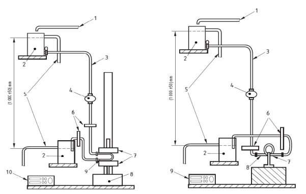
Figure 16 Short Term (LHS) and Long Term (RHS) Test methods for kinking single lumen catheters and medical tubing’s European Standard, (2002). Catheters – Test methods for kinking of single lumen catheters and medical tubing. BS EN 13868:2002.
6. Proposed Mathematical Methods for Determining Optimal Test Method significant factors.
1. Analysis of Variance (ANOVA) Testing.
The analysis of variance method determines if groups (related or unrelated) are statistically significant to each other. In order to carry out an ANOVA test, a hypothesis must first be determined. A hypothesis is a standard procedure about testing a claim about a property of a population. First a null hypothesis is formed. The Null hypothesis will test the significance of the hypothesis by either rejecting or failing to reject the claim of the null hypothesis. The Null hypothesis will claim that no difference exist between the population and the alternative hypothesis will claim that a difference exists between the populations. The alternative hypothesis will state that one or more of the parameters involved in a population will differ from the null hypothesis.
The next step in an ANOVA test is to determine if the null hypothesis should be rejected or is it better to fail to reject the null hypothesis. In order to do so, an understanding of a type 1 and type 2 error is needed. A type 1 error is when the null hypothesis is rejected when in fact it should be accepted. The symbol α is used to represent a type 1 error. A type 2 error is the mistake of failing to reject the null hypothesis when in fact it is false. The symbol to represent a type 2 error is β.
In order to determine when the results are statistically significand and when the null hypothesis should be rejected, then p < α, therefore the result is statistically significant and the null hypothesis should be rejected.
If p > α, then the null hypothesis should fail to be rejected and the results are statistically insignificant.
Lacey, S. (2017). Mathematics for Engineers 402.
2. Analysis of Variance (ANOVA) Examples.
To show how the ANOVA method can be applied to the parameters involved in determining the kinking limit of catheters and which factors attribute to the kinking limit the most i.e. which are statistically significant or insignificant, an example where an experiment was undertaken to test the effect of temperature and bar size on the UTS of a weld. The results from the experiment are show below in figure 16 and analysis of variance was carried out in order to determine the level of significance each parameter had on the strength of a weld. Lacey, S.
(2017). Mathematics for Engineers 402.

Figure 17 Analysis of Variance Example – Dr. Sean Lacey, 2016, Mathematics for Engineers 402.

Figure 18 Analysis of Variance Example – Dr. Sean Lacey, 2016, Mathematics for Engineers 402.

Figure 19 Analysis of Variance Example – Dr. Sean Lacey, 2016, Mathematics for Engineers 402.

Figure 20 Analysis of Variance Example – Dr. Sean Lacey, 2016, Mathematics for Engineers 402.
7. Material Properties of Neurovascular Catheters
Advanced catheters are engineered to perform an increasing number of minimally invasive surgeries. They must be able to guide their way through the intricate pathways of the neurovascular, cardiovascular and other anatomies. In order to achieve these demands, using ultra small catheters of 0.5 mm, the design must be near perfect and material selection for this design is key. Catheters consists mainly of 3 layers, the liner, the braiding and the outer sheath. They can be made up to lengths ranging from 900mm – 1200 mm. the best material for use in catheters are fluoropolymers such as PTFE and FEP due to their biocompatibility and lubricous properties. PTFE is the most lubricous polymer on the market today followed by FEP. The materials can undergo secondary processing steps such as etching and cutting, along with post extrusion expansion such as heat-shrinking.
The liner layer mainly is made from PTFE for it lubricity, ability to maintain a thin wall and have a small diameter.
The braid reinforcement layer is mainly made from Type 304 or 306 stainless steel. This layer increase is strength and rigidity without kinking the catheter. It increases the rigidity at the proximal end with a smaller pitch between winds and decrease rigidity at the distal end with a larger pitch between winds. This is done to provide greater torque transition from the proximal to distal tip of the catheter. The coil provides a greater kink resistance to the catheter along with reinforcing the catheters liner against ovalization by maximising the hoop stress.
The outer sheath is made up of high performance materials such as Pebax, FEP, PTFE, ETFE, polyurethane, polyethylene and nylon. Mddionline.com. (2016). Think Extrusion and Beyond for Optimal Catheter Design | MDDI Medical Device and Diagnostic Industry News Products and Suppliers.
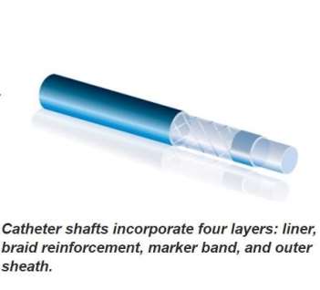
Figure 21 Material layers of a Neurovascular Catheter. Mddionline.com. (2016). Think Extrusion and Beyond for Optimal Catheter Design | MDDI Medical Device and Diagnostic Industry News Products and Suppliers.
Cite This Work
To export a reference to this article please select a referencing stye below:
Related Services
View all


DMCA / Removal Request
If you are the original writer of this essay and no longer wish to have your work published on UKEssays.com then please click the following link to email our support team:
Request essay removal