Alternator and Parallel Operation Experiment
| ✅ Paper Type: Free Essay | ✅ Subject: Engineering |
| ✅ Wordcount: 1208 words | ✅ Published: 30 Aug 2017 |
a) Purpose
In first part, the purpose is measuring the mechanical and iron losses of a synchronous generator or alternator which is most commonly used machine for generation of electrical power for commercial purpose.
In second part, the purpose is determining the ohmic and stray losses of a alternator at various speeds and calculating synchronous reactance.
In the last part, the purpose is measuring the response of the alternator (which is operating with the constant excitation and speed) under different kinds of load.
b) Background and Theoretical Discussion
The most commonly used machine for generation of electrical power for commercial purpose is the synchronous generator or alternator. An alternator works as a generator when its rotor carrying the field system is rotated by a prime-mover which in this case is DC shunt motor. The terminal voltage of an alternator changes with load.
Alternators are by far the most important source of electric energy. Alternators generate an AC voltage whose frequency depends entirely upon the speed of rotation. The generated voltage value depends upon the speed, the dc field excitation and the power factor of the load.
As the DC field excitation of an alternator is increased, its speed being held constant, the magnetic flux, and hence, the output voltage, will also increase in direct proportion to the current. However, with progressive increases in DC field current, the flux will eventually reach a high enough value to saturate the iron in the alternator. Saturation in the iron means that there will be a smaller increase in flux for a given increase in DC field current. Because the generated voltage is directly related to the magnetic flux intensity, it can be used as a measure of the degree of saturation.
When an alternator delivering full rated output voltage is suddenly subjected to a short-circuit, very large currents will initially flow. However, these large short-circuit currents drop off rapidly to safe values if the short-circuit is maintained. The output voltage of an alternator depends essentially upon the total flux in the air-gap. At no load this flux is established and determined exclusively by the DC field excitation.

Under load, however, the air-gap flux is determined by the ampere-turns of the rotor and the ampere-turns of the stator. The latter may aid or oppose the MMF (magnetomotive force) of the rotor depending upon the power factor of the load. Leading power factors assist the rotor, and lagging power factors oppose it.
The open-circuit test or the no-load test, is performed by driving the generator at its rated speed while the armature winding is left open. The field current is varied in suitable steps and the corresponding values of the open-circuit voltage varied in suitable steps and corresponding values of the open-circuit voltage between any two pair of terminals of the armature windings are recorded. The OCC follows a straight-line relation as long as the magnetic circuit of the synchronous generator does not saturate. In the linear region, most of the applied mmf is consumed by the air-gap; the straight line is appropriately called the air-gap line. As the saturation sets in, the OCC starts deviating from the air-gap line.
c) Procedure
In first part, after assemble the circuit according to the foregoing topographic diagram, exciter current and the current and voltage absorbed by the dc motor measured when not coupled to the alternator. Then motor and alternator coupled to measure exciter current and the current and voltage absorbed by the dc motor again. In this stage, it is an important point that alternator was not excited, so power between these two measurement gives us mechanical losses of the alternator.
In the end, stator voltages for three speeds as a function of the exciter currents measured(Table 1) when the alternator is running at different constant speeds.
In second part, after assemble the circuit according to the foregoing topographic diagram, exciter current and the current and voltage absorbed by the dc motor measured when alternator stator winding is short-circuited. After that, short-circuit current measured (Table 2) corresponding to the alternator exciter current values when the alternator is running at different constant speeds.
In the last part, after assemble the circuit according to the foregoing topographic diagram, the resistive load was used as the first load, after that experiment repeated with inductive loads and finally with capacitive loads too. Load are connected in star connection. It could be connected as delta connection too but preferred as star connection because the alternator is already connected in star connection too. After loads connections set, value of the dc supply voltage of motor-alternator set increased until nominal speed of the alternator is reached. With the no-load exciter current IE0 (which were founded in first part of the experiment) given to the alternator field, measurements was starts with steps from R1 to R5 value. After that resistive load replaced and measurements repeated for inductive and capacitive loads too (Table 3).
d) Results
IEM= 0.8 AIM= 1.38 AUM= 220 VPMm= UM(IM – IEM) = 127.6 W
IEM0= 0.8 AIM0= 1.84 AUM0= 220 VPM0= UM0(IM0 – IEM0) = 228.8 W
PGm= PM0 – PMm = 101.2 WIE0= 250 mA
|
Speeds(min-1) |
3000 |
2500 |
2000 |
|
IE (mA) |
US (V) |
US (V) |
US (V) |
|
100 |
27 |
37 |
35 |
|
200 |
213 |
168 |
163 |
|
250 |
393 |
337 |
254 |
|
300 |
457 |
392 |
315 |
|
350 |
512 |
444 |
351 |
|
400 |
545 |
473 |
379 |
|
450 |
578 |
497 |
395 |
|
500 |
595 |
516 |
412 |
|
550 |
613 |
530 |
425 |
Table 1 : Stator voltage corresponding to the following exciter current values when alternator is running at different constant speeds.
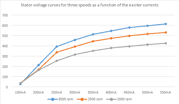
Plot 1 : Stator voltage curves for three speeds as a function of the exciter currents
IEMk= 1 AIMk= 1.95 AUMk= 214 VPMk= UMk (IMk – IMEk) = 203.3 W
|
Speeds(min-1) |
3000 |
2500 |
2000 |
|
IE (mA) |
US (V) |
US (V) |
US (V) |
|
100 |
0.1 |
0.1 |
0.2 |
|
200 |
0.3 |
0.4 |
0.5 |
|
250 |
0.6 |
0.7 |
0.75 |
|
300 |
1.0 |
1.15 |
1.0 |
|
350 |
1.3 |
1.3 |
1.25 |
|
400 |
1.5 |
1.51 |
1.5 |
|
450 |
1.7 |
1.7 |
1.75 |
|
500 |
2 |
2.0 |
2.0 |
|
550 |
2.25 |
2.3 |
2.25 |
Table 2 : Short-circuit current corresponding to alternator exciter current values when the alternator is running at different constant speeds.
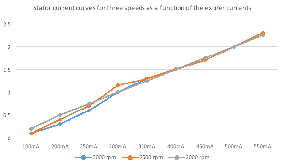
Plot 2 : Stator current curves for three speeds as a function of the exciter currents
|
n= 3000 (min-1) IE0= 250 (mA) |
||||||||
|
R |
IS (A) |
US (V) |
L |
IS (A) |
US (V) |
C |
IS (A) |
US (V) |
|
R1 |
0.1 |
368 |
L1 |
0 |
333 |
C1 |
0.1 |
437 |
|
R2 |
0.2 |
357 |
L2 |
0.1 |
316 |
C2 |
0.2 |
466 |
|
R3 |
0.4 |
323 |
L3 |
0.2 |
278 |
C3 |
0.5 |
513 |
|
R4 |
0.5 |
284 |
L4 |
0.3 |
243 |
C4 |
0.8 |
576 |
|
R5 |
0.6 |
234 |
L5 |
0.4 |
211 |
C5 |
1.1 |
609 |
Table 3 : Stator current and voltage corresponding to different load values when the alternator is running at constant speeds and constant no-load exciter current value
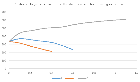
Plot 3 : Stator voltages as a funtion of the stator current for three types of load
e) Conclusions
In first part, it is possible that, learning about some machine characteristics with no-load test such as mechanical losses and the iron losses of alternator. In addition to that, it is observered that (Plot 1), with constant excitation the no-load voltage is proportional to the speed.
In second part, just like in first part it is possible that, learning about some machine characteristics with short-circuit test such as ohmic and stray of alternator. Also, theoretically it is possible that synchronous reactance could be calculate In addition to that (Plot 2), it is observered that, short-circuit current is independent of the speed of the alternator and is proportional to the exciter current.
In last part, the response of the alternator (which is operating with the constant excitation and speed) measured under different kinds of load. As expected, under capacitive load the stator voltage increases with increasing current, whereas under resistive and inductive loads it drops. Furthermore, in the case of inductive load a more sever voltage drop can be observed than under resistive load (Plot 3).
f) References
1. A.E. Fitzgerald, C. Kingsly, Jr., and S.D. Umans, Electrical Machines, 5th edition, McGraw-Hill New York, 1990.
2. D.P. Kothari, I.J. Nagrath, Electrical Machines, Tata McGraw-Hill, 2004
Cite This Work
To export a reference to this article please select a referencing stye below:
Related Services
View all


DMCA / Removal Request
If you are the original writer of this essay and no longer wish to have your work published on UKEssays.com then please click the following link to email our support team:
Request essay removal